How to read this study
| Known from the project account | 150 m³/h duty; reported head restoration from 38 to 45 m; radial clearances 0.9 and 0.3 mm. |
|---|---|
| Assumed for the worked example | Wear-ring diameter, leakage coefficient, pressure drop and model geometry. |
| Check on the reasoning | Head and hydraulic-power balances; controlled re-test described in the account. |
| Still to verify | Original test readings, actual leakage and complete pump characteristic. |
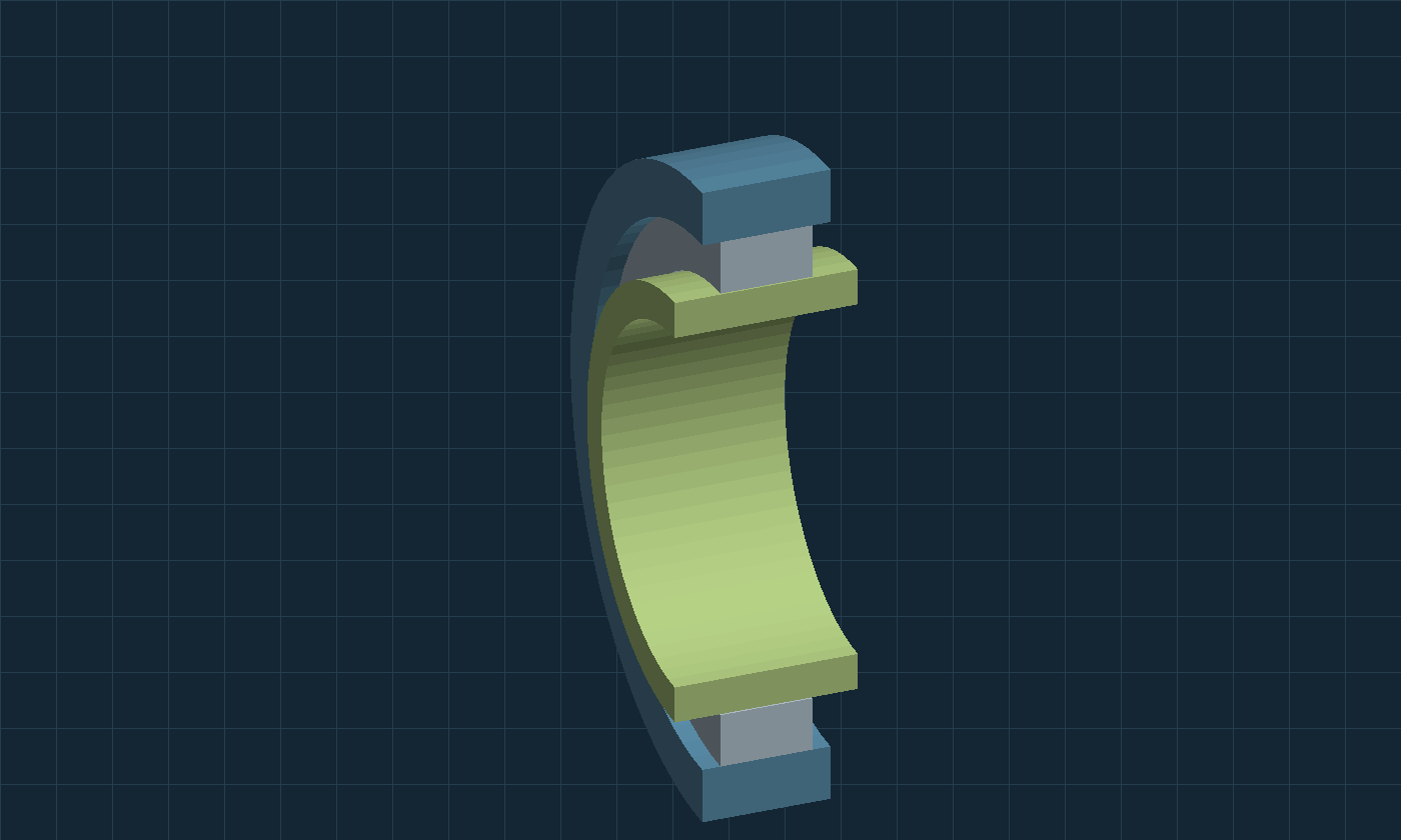
Follow the diagnosis from the failed duty point to the wear-ring interface, then compare the two clearances in 3D below.
Inspect the interface ↗A failed test is evidence. Start by deciding what it proves.
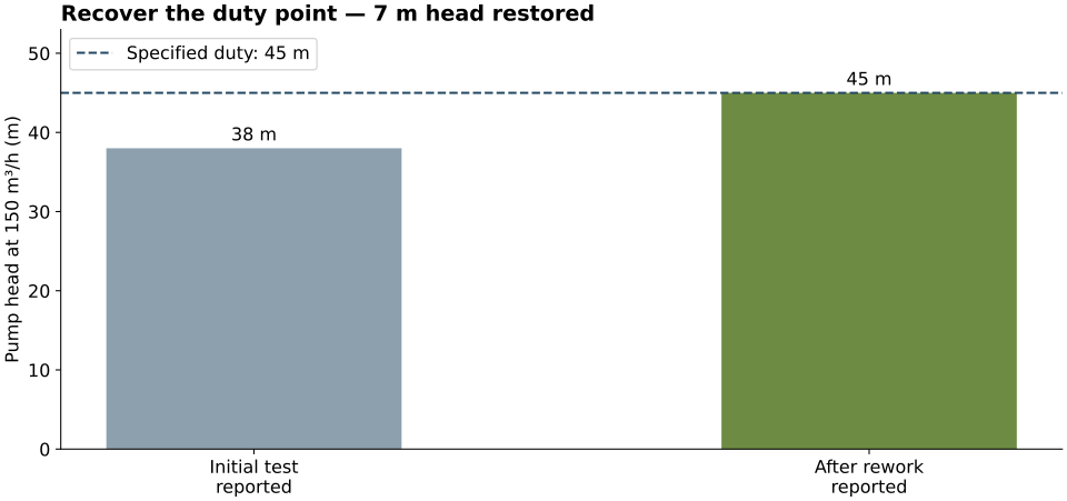
A centrifugal pump ordered for 150 m³/h at 45 m head produced only 38 m at the stated flow during its initial test. That is a 7 m deficit, or 15.6% below the required head. The engineering task was to recover the specified duty while protecting the approved design intent.
I checked the measurement arrangement and rotational speed before changing the pump. Inspection then identified a 0.9 mm impeller-to-wear-ring radial clearance against a specified 0.3 mm. The corrective action was a replacement wear ring, reviewed and approved by the senior engineer, followed by dimensional verification and a repeated performance test. The reported result was restoration of the duty, with motor loading confirmed within the 30 kW rating.
The duty, clearance findings and reported outcome above come from the project account. The dimensioned interface model and worked examples below explain the reasoning using explicit assumptions; they are not additional test records.
Correct the manufacturing non-conformance before considering a change to the approved hydraulic design.
1. Head is energy per unit weight.
Pressure is only one part of the energy carried by a moving liquid. To compare the suction and discharge sides of a pump, include pressure, elevation and velocity. For steady incompressible flow between the measurement sections:
Use consistent pressure references. Two gauge readings can be subtracted; a gauge reading must not be directly subtracted from an absolute reading. Use internal pipe diameters to calculate velocity from flow. Pressure-tap elevations and instrument locations must be documented.
Worked measurement example: assume water at ρ = 998 kg/m³, equal internal diameters at the two measurement sections, a discharge tap 0.50 m above the suction tap, and a differential pressure of 435.5 kPa. Equal velocities cancel:
H ≈ 45.00 m
This example reconstructs a head calculation; it does not supply the original gauge readings. If the measurement sections are remote from the pump flanges, account for intervening losses and the agreed test boundary. Head is an energy quantity, so a pressure-only calculation can misdiagnose a pump.
2. Eliminate measurement causes before opening the machine.
A disciplined investigation follows the energy path. First establish whether the shortfall is real, then find where it can arise.
- Confirm the duty definition. Establish flow, fluid properties, speed, impeller configuration and the purchase acceptance requirements.
- Check the test arrangement. Review instrument calibration, pressure-tap condition, trapped air, zero offsets, flow-meter installation and straight lengths required for the particular meter.
- Verify the operating state. Check speed and rotation, priming, valve positions and suction conditions. Cavitation or air entrainment can reduce head, but a low reading alone does not identify either.
- Inspect the hydraulic interfaces. Measure the wear-ring bore and rotating land, check impeller dimensions, assembly position and signs of rubbing or damage.
- Change one controlled cause. Record the rework, preserve configuration traceability and repeat the comparison at the same defined duty.
This order prevents a design change from hiding a measurement error or a machining defect. It also makes the subsequent before-and-after comparison more persuasive.
3. The small gap that connects two pressure regions.
A wear ring provides a restricted path between the higher-pressure region and the impeller inlet region. The rotating land and stationary bore must remain clear in service, but excess clearance makes internal recirculation easier.
The 3D study isolates that interface: a rotating land, a replaceable stationary ring and a simplified housing seat. Its assumed land diameter is 120.00 mm. The two ring bores reproduce the reported radial clearances exactly.
Loading the CAD mesh…
Green: rotating land · Grey: stationary wear ring · Blue: housing seat. The model uses true-scale gaps; use the expanded section below to read the small clearance.
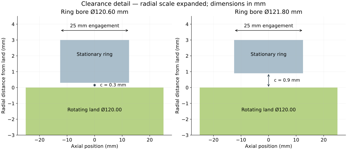
Restored: (120.60 − 120.00)/2 = 0.30 mm
Oversize: (121.80 − 120.00)/2 = 0.90 mm
The 0.60 mm and 1.80 mm differences are diametral clearance. Confusing them with radial clearance doubles the error. This is an interface study: the housing seat is nominal geometry, with no production interference fit or retention detail specified.
4. Derive a useful leakage estimate—and know its limit.
For a narrow annular passage, the area perpendicular to axial leakage is approximately circumference times radial gap:
At c = 0.30 mm: A ≈ π × 0.120 × 0.00030
A ≈ 1.131 × 10⁻⁴ m²
The exact concentric annulus area is π(Dc + c²); πDc neglects the smaller c² term. A first sensitivity estimate treats the restriction as an equivalent orifice:
For an explicitly assumed Δp = 250 kPa, Cd = 0.62 and ρ = 998 kg/m³:
c = 0.90 mm → Qleak ≈ 16.95 m³/h
Tripling the gap triples leakage in this fixed-pressure, fixed-coefficient approximation. The actual restriction has length, friction, entrance losses, eccentricity, rotation and possibly grooves. Those features affect the effective coefficient and pressure distribution; the 25 mm engagement length is not explicitly solved by this orifice model.
The pump must process both delivered and internally recirculated flow. A simplified volumetric delivery fraction is Q/(Q + Qleak): at 150 m³/h delivery, this gives 96.37% for the smaller gap and 89.85% for the larger gap. These values illustrate a mechanism; they are not measured pump efficiencies.
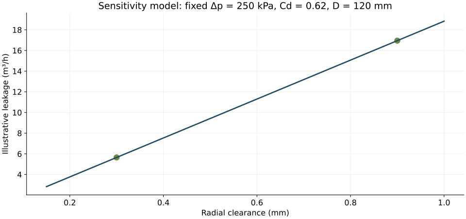
This calculation does not predict the observed 7 m head recovery. A quantitative prediction needs the impeller characteristic, internal flow paths and their coupling to the operating point. The controlled rework and repeat test provide the performance evidence.
5. Recovering head changes the useful power.
Hydraulic output power follows directly from energy conservation: mass flow multiplied by specific energy. With Q = 150/3600 = 0.041667 m³/s:
At 38 m: Phyd = 15.50 kW
At 45 m: Phyd = 18.35 kW
Recovered useful hydraulic output ≈ 2.85 kW
That is useful output at the stated duty, not a direct claim of electrical energy savings. Shaft input is Phyd/ηpump; electrical input includes motor and drive losses as well.
If pump efficiency at the restored duty were 75%—a teaching assumption—the required shaft power would be 18.35/0.75 = 24.47 kW. Relative to a 30 kW motor shaft-output rating, the arithmetic difference is 5.53 kW. This does not replace a motor-loading review across the operating envelope. The original case reports that loading was verified, but does not provide a measured efficiency value.
A motor-current reading alone is not a shaft-power measurement. A proper assessment distinguishes electrical real power, motor efficiency, drive losses and mechanical output.
6. Clearance is a tolerance-and-materials problem.
The smallest possible cold clearance is not automatically the best operating clearance. The design must allow for differential thermal growth, shaft deflection, runout, misalignment and transient motion while restricting leakage.
Illustrative tolerance stack: let the stationary bore be 120.60 ± 0.03 mm and the rotating land be 120.00 ± 0.02 mm. Worst-case cold radial clearance is:
cmax = (120.63 − 119.98)/2 = 0.325 mm
These assumed tolerances demonstrate the stack; they are not a proposed release specification. A nominal 0.30 mm requirement needs its actual allowable range defined. Measure at multiple angular positions and axial locations to detect ovality and taper, rather than accepting one favourable reading.
For thermal growth, the first-order clearance change is approximately ½(αringDboreΔTring − αlandDlandΔTland). With assumed coefficients of 18 and 12 µm/(m·K), equal 50 K rises and the study diameters, the gap opens by about 0.0183 mm. Different temperatures or material pairs can close it instead. The housing restraint makes a full assessment more involved than free expansion alone.
Material selection should consider the pumped fluid, corrosion, abrasive particles, temperature, hardness pairing, galling resistance and replaceability. Bronze, metallic alloys or engineered polymers can be candidates in suitable applications; none is a universal choice. The project account does not specify the actual ring grade, so this study does not assign one.
The housing must also retain the ring under pressure and service loads. Interference, shoulders or other retention features require their own drawing and review. A concentric CAD fit demonstrates geometry, not retention capacity.
7. Why a bigger impeller was the wrong first answer.
Increasing impeller diameter or speed may increase head, but it also changes the approved hydraulic configuration and the power demand. It leaves the oversized leakage path in place.
For the same impeller at corresponding dynamically similar operating points, the speed affinity relationships are Q ∝ n, H ∝ n² and P ∝ n³. A hypothetical head scaling from 38 to 45 m would require:
Q₂/Q₁ ≈ 1.088; P₂/P₁ ≈ 1.289
This is roughly 8.8% more speed and 28.9% more power at the corresponding point, assuming similar efficiency. It does not establish 45 m at the original 150 m³/h on the actual system curve. Impeller trimming or enlargement is also not exactly equivalent to speed scaling; use the manufacturer’s curves and mechanical limits.
The rational sequence was therefore to restore the specified clearance, repeat the test and reassess only if the duty remained unmet. This kept the corrective action proportional to the evidence.
8. Explore the clearance sensitivity.
Change the assumed gap and restriction pressure. The result shows leakage sensitivity only; the model does not generate an acceptance curve.
Fixed assumptions: D = 120 mm, Cd = 0.62, ρ = 998 kg/m³, delivered flow = 150 m³/h. Sensitivity controls do not alter the dimensioned CAD configurations.
9. Close the loop with an inspection and a repeatable test.
Dimensional conformity and hydraulic acceptance answer different questions. The inspection proves the gap was restored. The test proves the assembled pump meets the agreed duty under the defined conditions. Neither is a substitute for the other.
- Disposition: identify the non-conforming component, document the finding and obtain the required engineering approval.
- Dimensional inspection: record ring bore and land diameter, radial clearance, roundness, taper, concentricity and relevant assembly checks.
- Controlled assembly: verify retention, cleanliness, free rotation and the intended impeller configuration.
- Repeat hydraulic test: record flow, pressure readings, tap elevations, speed, fluid temperature and the loading measurement method. Stabilize the test before recording each point.
- Acceptance decision: apply the purchase specification and agreed test standard, grade, tolerances and uncertainty treatment. Do not choose a favourable grade after seeing the result.
- Prevention: make clearance verification a documented in-process inspection point before final assembly.
ISO 9906 addresses hydraulic performance acceptance testing of rotodynamic pumps. The project references it, but the available account does not identify an acceptance grade or provide the original test sheet. No numerical ISO pass band is invented here.
A strong design review connects a measured symptom to a physical mechanism, a controlled corrective action and a repeatable verification. The result is more valuable when the inspection plan prevents the same loss from returning.
10. Inspect the geometry and calculations.
STEP exchange models can be imported into compatible CAD software. Both configurations contain three valid solids. The package includes mesh versions and a readme explaining the study boundary.
Further reading
- KSB Pump Lexicon: shaft motion and clearance gaps
- KSB Pump Lexicon: pump affinity laws
- KSB Pump Lexicon: drive rating
Continue the related studies: Cavitation Control · Shaft Redesign · Pressure Integrity.