How to read this study
| Known from the project account | Casing verification through analysis, review and pressure testing. |
|---|---|
| Assumed for the worked example | Study geometry, pressure, material parameters and analytical benchmark results. |
| Check on the reasoning | Pressure equilibrium and analytical stress/deformation checks. |
| Still to verify | Full-casing FEA, actual material specification and original test records. |
The job is to explain where the load goes.
A revised centrifugal-pump casing needed verification for higher-pressure service. The discharge-nozzle transition deserved particular attention: a curved pressure boundary meets a stiffer flange, while the connected pipe can apply forces and moments of its own.
My project approach combined pressure loading of the wetted surfaces, material and restraint definition, local mesh refinement, independent pressure-force and stress checks, and comparison with the manufacturing drawing. Senior-engineer review was followed by a hydrostatic test and inspection for leakage or permanent deformation.
This article develops that reasoning through a new, dimensioned pressure-boundary study. The original project establishes the verification approach; the dimensions, pressure and numerical results below are explicit teaching assumptions. The new calculations are analytical benchmarks, not newly measured test results or a solved full-casing FEA.
Can we explain equilibrium, deformation and failure at every important interface—and show that three different checks tell a consistent story?
1. Three principles beneath every stress plot.
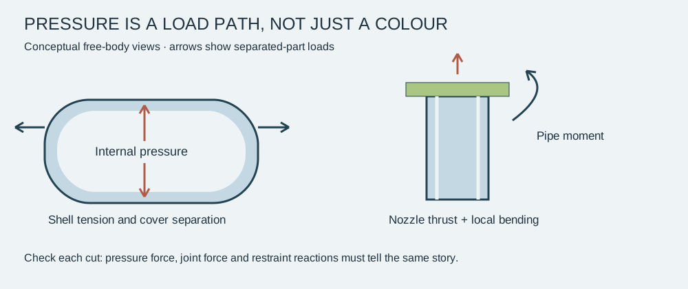
Equilibrium: forces and moments must balance. A pressure field is a distributed surface traction. Integrating it over the relevant projected area gives the resultant load. Restraint reactions should close the same free-body diagram.
Compatibility: connected material cannot deform arbitrarily. A flexible shell and a stiff flange must meet at the same displacement and rotation. That constraint creates local bending even when pressure is uniform.
Constitutive behaviour: the material relates stress to strain. In an isotropic linear-elastic approximation, E controls stiffness and ν couples strain directions. Yield strength is a different property: it concerns permanent deformation, not elastic flexibility.
Elastic response: {σ} = [D]{ε}
Finite elements: [K]{u} = {F}
A solver discretizes these relationships. It does not decide whether the material, contacts, load cases or acceptance criteria represent the real assembly. Before trusting a colour contour, predict which part should expand, bend, rotate or separate.
2. Define the design basis before the mesh.
| Quantity | Example value | Meaning |
|---|---|---|
| Internal pressure | 1.20 MPa = 12 bar gauge | Uniform differential pressure; teaching assumption |
| Chamber radii | 150 mm internal / 160 mm external | 10 mm nominal wall |
| Straight chamber length | 120 mm | Short pressure-boundary surrogate |
| Cover thickness | 20 mm | Blind rear cover used for plate benchmark |
| Discharge nozzle | 100 mm ID / 124 mm OD | Local tube section for nominal load checks |
| Cover fasteners | 12 positions on a 350 mm bolt circle | Simplified 12 mm stud geometry; no thread specification |
| Elastic model | E = 200 GPa; ν = 0.30 | Generic steel-like elastic example; no material grade selected |
| Nozzle moment | 300 N·m | Illustrative external piping moment |
| Joint assumptions | 15 kN preload/bolt; C = 0.20 | Teaching values, not a tightening specification |
Design pressure must cover the applicable operating envelope: maximum suction pressure plus the relevant pump differential pressure, shutoff conditions, transients and temperature. Normal operating pressure alone is not a complete design basis. Establish the governing product specification and service requirements before assigning allowable stress or a test pressure.
The CAD chamber is cylindrical so its mechanics are easy to audit. It is not a hydraulic volute: no tongue, impeller passage or efficiency claim is implied. Its short length and large nozzle opening also mean that a long-cylinder solution is a benchmark, not an exact stress solution for this assembly.
3. Inspect the pressure boundary in section.
The assembly includes a hollow chamber, a discharge nozzle with a local reinforcement boss, drilled flanges, two covers, an axial inlet, studs, nuts and mounting feet. Start with the section view to see the 10 mm wall and continuous pressure passage; switch to the full assembly to inspect the external interfaces.
Loading the CAD mesh…
Blue: pressure body and nozzles · Green: covers and discharge flange · Grey: fasteners and supports. Drag to rotate; dimensions in mm.
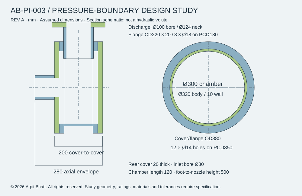
The boss is a candidate load-spreading feature, not a demonstrated optimum. Junctions are idealized; final blend radii, casting draft, machining allowances, gasket grooves, fits, thread engagement and flange ratings require detailed design. Sharp junctions in this study must not be treated as converged FEA peak-stress locations.
4. Pressure becomes force through projected area.
Imagine cutting through the discharge nozzle and replacing the connected piping with its equivalent loads. The closed-end pressure thrust associated with the 100 mm bore is:
Fnozzle = 1.20 × π × 100²/4 = 9,425 N
Fcover = 1.20 × π × 300²/4 = 84,823 N
MPa is N/mm², so these equations use millimetres directly. The cover load is approximately 8.5 tonnes-force in magnitude, even though the pressure number itself looks modest. It must travel through the cover, joint and casing.
For a truncated FEA model, include the correct equivalent pressure-end loads and mechanical pipe loads. If a closed cap is already modelled and pressurized, adding its pressure thrust again double-counts that load. Pressure on all faces of a fully closed surface is globally self-equilibrating; that does not eliminate the large internal forces across a cut.
5. First estimate: membrane stress in the wall.
Split an ideal cylinder along its axis. Pressure on the projected diameter-length area is balanced by tension in the two cut walls. Split across a closed end, and pressure thrust is balanced by axial tension around the annulus.
σz ≈ pr/(2t) = 9.00 MPa
The hoop stress is approximately twice the axial stress in this ideal thin-wall case. These are membrane stresses: load carried largely by in-plane tension. Bending stress varies through the thickness and is superimposed near geometric discontinuities or flexible covers.
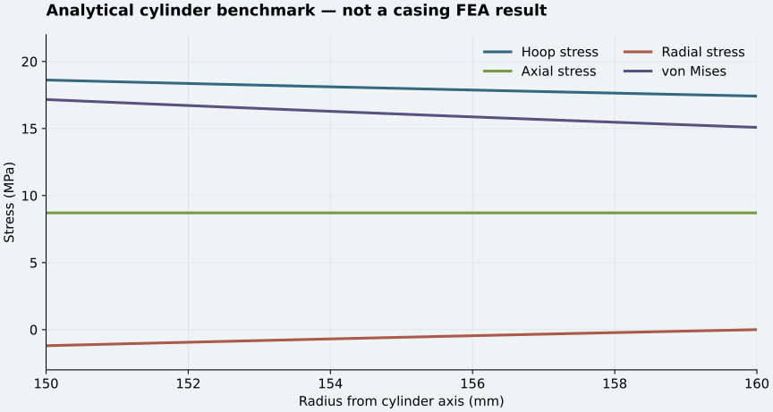
With t/r = 0.0667, the thin-wall result is a useful first check. We can improve it using Lamé’s thick-cylinder solution, treating external differential pressure as zero:
σr(r) = A − B/r²
σθ(r) = A + B/r²
σz = A (closed-end cylinder)
| At the inner surface | Calculated value |
|---|---|
| Hoop stress σθ | 18.619 MPa |
| Axial stress σz | 8.710 MPa |
| Radial stress σr | −1.200 MPa |
| von Mises equivalent stress | 17.164 MPa |
| Radial displacement | 0.01227 mm, with assumed E and ν |
The hoop prediction is only 3.44% above the thin-wall value. That agreement is a useful scale check. It does not validate the nozzle junction: the cylindrical solution assumes axisymmetry and excludes local openings, cover flexibility and mounting effects.
6. A stress number needs a failure criterion.
For a ductile, isotropic metal, von Mises stress is commonly used to screen first yield. It is built from differences between principal stresses, rather than the hydrostatic mean stress. At the inner wall, retaining radial compression changes the equivalent stress; setting σr to zero is an approximation.
Grey cast iron behaves differently in tension and compression and has limited tensile ductility. A ductile-metal yield check alone is not an adequate failure assessment. Principal tensile stresses, material-specific brittle-failure criteria, casting quality and the applicable design rules matter.
Strength, stiffness, fatigue resistance and fracture toughness answer different questions. A stronger grade need not have a proportionally larger Young’s modulus. A low static stress does not rule out cracking from defects or repeated local strain. Use the certified grade and properties at temperature; no allowable stress or overall safety factor is claimed from the generic elastic values here.
7. The cover may govern before the shell does.
A flat cover cannot carry transverse pressure by cylindrical hoop action alone. It bends. As an independent benchmark, idealize the blind cover as a uniformly loaded circular plate, fully clamped at a 150 mm radius, with thickness h = 20 mm.
w₀ = pa⁴ / (64Dplate) = 0.0648 mm
|σr,edge| = 3pa²/(4h²) = 50.625 MPa
The maximum radial bending-stress magnitude at the ideal clamped edge is already larger than the cylinder’s nominal hoop stress. This is not a stress comparison at the same location or under identical boundary assumptions—it shows why a wall-only calculation can miss the controlling mechanism.
The actual bolted cover is not perfectly clamped. Gasket stiffness, bolt spacing, preload and flange rotation alter its boundary condition. A detailed contact model must check local bending, bolt prying and separation. The front cover has an opening, so this solid-plate formula is not directly applicable to it.
In this plate model, bending stress scales with 1/h² and deflection with 1/h³. Thickness is powerful, but a stiffer cover can also redistribute force into bolts and the flange. Recheck the joint after changing the cover.
8. Nozzle loads expose the limits of nominal stress.
The discharge neck is also a short hollow beam. For its 62 mm outer and 50 mm inner radii, an illustrative 300 N·m piping moment produces:
Z = I/ro = 108,009 mm³
σb = M/Z = 300,000/108,009 = 2.778 MPa
σaxial,pressure = F/Ametal = 2.232 MPa
The tensile-side nominal axial sum is about 5.010 MPa before local effects. It excludes circumferential stress, radial stress, shear and the three-dimensional transition into the casing. Do not add this value to the chamber’s 18.619 MPa hoop stress as though they were the same stress component at the same location.
A nozzle opening interrupts the shell load path. A boss, gradual wall transition or fillet can spread the load, but a large local stiffness change can shift the hot spot. Compare alternatives at consistent load, thickness basis, mesh resolution and stress-extraction locations. Include the full six-component piping load set when the real installation requires it.
9. Bolts are springs in a clamped system.
Dividing pressure thrust by bolt count gives an external load per position, not the final bolt tension. In a simple concentric joint that remains closed, the bolt and clamped members share the load increment according to their stiffness.
C = kb/(kb+km)
Fbolt = Fi + CFe
Fclamp = Fi − (1−C)Fe
With the illustrative Fi = 15 kN and C = 0.20, bolt tension becomes 16.414 kN and residual clamp force becomes 9.345 kN per position. These positive clamp forces are not a leakage acceptance criterion.
The real joint needs gasket seating and operating contact-pressure checks, bolt proof-strength and fatigue checks, flange flexibility, uneven loading, preload scatter, relaxation and prying. The effective gasket diameter can also change the pressure-separation load. Do not use the example preload as a torque instruction; thread geometry, lubrication and tightening control are not specified.
10. Select the material for the whole service.
Start with the fluid chemistry, temperature range, pressure cycles, solids, manufacturing route, inspectability and consequences of leakage. Then choose a material family and verify an actual grade. Selecting the highest yield strength from a software library is not material selection.
| Candidate family | Why consider it | Questions before selection |
|---|---|---|
| Grey cast iron | Castability, machinability and vibration damping | Tensile brittleness, impact/thermal duty, casting defects and service restrictions |
| Ductile iron | Greater ductility than grey iron in suitable grades | Grade, section-dependent properties, temperature limits and fluid compatibility |
| Cast carbon steel | Ductile pressure-boundary candidate | Corrosion allowance, heat treatment, casting quality and repair requirements |
| Cast stainless steel | Candidate where corrosion resistance is needed | Actual chemistry, chlorides, temperature, pitting/crevice risk, galling and cost |
For a non-aggressive water-service teaching model, a ductile metallic candidate is a reasonable starting point for elastic analysis. Final selection remains open because fluid chemistry, temperature and certified grade data are missing. The assumed E = 200 GPa does not assign a particular steel grade to the CAD.
Thickness also needs a manufacturing and life-cycle budget. If 10 mm nominal wall loses an illustrative 2 mm corrosion allowance and 1 mm negative manufacturing allowance, only 7 mm remains for a structural screening calculation. These allowances are not requirements for this project; establish them from service and procurement data.
Abrupt thick bosses can complicate solidification and create shrinkage-prone regions. Smooth transitions, feeding strategy, machining datums and inspection access belong in the same design review as stress. Casting porosity or wall thinning can invalidate an otherwise attractive nominal model.
11. Advanced machine design starts with load combinations.
Fatigue: pressure cycling creates a stress range. In the linear Lamé benchmark, cycling from 0.20 to 1.20 MPa produces an inner-wall hoop range of 15.516 MPa, amplitude 7.758 MPa and mean 10.861 MPa. Local notch response, mean-stress treatment, surface condition, size, casting defects and the service cycle spectrum must be addressed before calculating life. A rotating shaft fatigue model cannot simply be copied onto a stationary casing.
Thermal restraint: a uniform temperature rise in a free part produces expansion without thermal stress. Under an ideal, fully restrained uniaxial condition, σ = EαΔT. Taking α = 12 × 10⁻⁶/K and ΔT = 40 K gives 96 MPa with the example E. This is a restraint demonstration, not a predicted casing stress; thermal gradients and real support flexibility require a coupled load assessment.
Local versus general stress: pressure-induced primary stress must satisfy equilibrium; compatibility stresses arise from constrained deformation. A sharp-notch peak can affect fatigue differently from the section-average membrane stress. Stress linearization separates membrane and bending components along a defined through-wall path, but requires the appropriate design framework and careful path placement.
Failure modes beyond yielding: consider gasket leakage, fatigue cracks, brittle fracture, mounting distortion, excessive flange rotation and external-pressure buckling if vacuum service is possible. Passing one criterion does not close the others.
12. Build an FEA model that can be challenged.
| Step | Engineering check |
|---|---|
| Geometry | Use the as-designed wall thickness, nozzle blending and relevant contact surfaces. Preserve features that change load paths. |
| Loads | Pressure on all wetted faces; justified end loads; piping forces/moments; weight; relevant thermal and transient cases. |
| Restraints | Represent mount and pipe flexibility. Avoid fully fixing every flange merely to remove rigid-body motion. |
| Contacts | Model cover/gasket separation, bolt preload and appropriate friction where they affect the answer. Bonded contact suppresses opening. |
| Mesh | Use suitable higher-order solids; resolve wall bending through thickness and refine nozzle/fillet/contact regions. Check element quality. |
| Solution checks | Reaction equilibrium, deformed shape, contact status and unit consistency before assessing peak stress. |
| Convergence | Track displacement and selected physical stress measures over at least three progressively refined meshes. Record location and extraction method. |
| Acceptance | Compare the relevant stress, deformation and joint measures with justified criteria for each load case. |
A singularity is not a small, highly stressed physical region that has merely been meshed poorly. At an ideal sharp corner or point restraint, the mathematical peak can keep rising as the mesh is refined. Restoring the physical radius or load distribution may resolve the idealization; arbitrarily hiding the red elements does not.
Monitor stress at a specified physical location or a justified through-wall path, alongside displacement and reactions. A trial 5% change threshold may be used as a study target, but it is not a universal acceptance rule. No invented mesh-convergence table or coloured “FEA result” is used here: the plotted stresses are labelled analytical cylinder results.
Linear scaling is valid only while material response is elastic and contact/load conditions do not change. If the joint opens, frictional slip changes or yielding spreads, pressure cannot simply be multiplied to infer the next solution.
13. Explore pressure and wall-thickness sensitivity.
This calculator updates the closed-end cylinder benchmark only. The CAD stays at its nominal 10 mm wall; changing the control does not redesign the nozzle, cover, bolts or model geometry.
Fixed inner radius 150 mm; outer radius = 150 + wall. Generic linear elasticity; no safety/pass indication.
14. Make three checks answer different questions.
| Method | What it contributes | What it cannot establish alone |
|---|---|---|
| Hand calculations | Load scale, equilibrium and independent shell/plate/joint benchmarks | Full three-dimensional stresses around the nozzle or contact behaviour |
| Finite elements | Spatial stress, deformation and load redistribution for the modelled conditions | Truth of assumed materials, geometry, loads or restraints |
| Hydrostatic test | Evidence of pressure containment and observable leakage/deformation for the tested article and conditions | Fatigue life, all internal defects, all thermal states or the validity of every FEA assumption |
For illustration, raising pressure from 1.20 to 1.80 MPa multiplies the elastic cylinder stresses by 1.5: inner hoop stress becomes 27.929 MPa. That number is a load-scaling exercise, not a prescribed test pressure. The applicable specification and approved test plan determine pressure, temperature, duration, instrumentation and acceptance criteria.
A hydrostatic test should be planned and performed by qualified personnel with rated equipment, controlled access and management of trapped air and stored energy. A portfolio calculation is not a test procedure. Record the pressure history and inspection findings, and compare pre-/post-test dimensions where permanent deformation is a concern.
The project’s reported outcome was agreement among the hand check, simulation and hydrostatic verification, followed by production release with a calculation trail. A strong review does not demand identical numbers from three methods with different scopes. It requires compatible evidence, explained differences and no unresolved failure mechanism.
The review package.
All added geometry and numerical inputs are illustrative. Use the dimension schedule, material certificate, service loads and governing requirements to develop a release-ready design.
Further reading
University of Washington: thick-cylinder mechanics
Ansys: assessing stress singularities
KSB: material selection
Discuss the design with Arpit → · Read Cavitation Control · Read Shaft Redesign