Manufacturing Clarity: From Design Intent to Shop Floor.
A custom self-priming pump had to fit fixed client flange positions and a specified motor frame.
Atlas Electricals · Design experience · By Arpit Bhatt
A drawing set is an agreement between disciplines
The self-priming pump had fixed client flange positions and a specified motor frame. Those interfaces made the general arrangement the starting point: the internal components had to work within an agreed installation envelope.
The work connected client review, detailed component drawings, assembly sections and a controlled BOM. The aim was to make design intent usable by fabrication, machining, fitting, inspection and future spare-parts support.
| Basis | Value / decision |
|---|---|
| Reported constraints | Fixed client flange positions, specified motor frame and maintenance access. |
| Reported deliverables | General arrangement; casing, shaft, impeller and bearing-housing drawings; assembly sections; BOM. |
| Resolved issue | Coupling-guard access conflict; fitter feedback on seal installation incorporated. |
| Worked example | A three-dimension axial location chain and a simple cylindrical clearance fit, with assumed tolerances. |
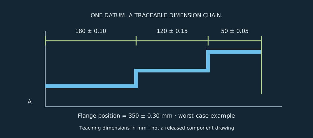
Derive the tolerance stack before releasing parts
For the example flange location, let X = A + B + C, measured from one mounting datum. Nominal dimensions add directly. Worst-case variation follows from putting every contributing size at its extreme in the same direction.
X = 350 mm
Tworst case = 0.10 + 0.15 + 0.05 = 0.30 mm
Xmin = 349.70 mm; Xmax = 350.30 mm
If the client’s example interface permits only 350 ± 0.20 mm, these part tolerances cannot guarantee assembly compliance. Possible responses include reducing the dominant tolerance, machining from a shared datum, using an approved adjustment feature or measuring the final assembly directly. The best response depends on manufacturing capability and cost.
A root-sum-square value is √(0.10² + 0.15² + 0.05²) = 0.187 mm. It is a statistical estimate only if the contributions represent independent, centred variation at a common statistical coverage. Drawing limits do not establish that distribution. RSS cannot be used as a substitute for a guaranteed worst-case limit.
Make fits explicit and inspectable
A cylindrical clearance is the hole diameter minus the shaft diameter. The smallest clearance pairs the smallest hole with the largest shaft; the largest pairs the largest hole with the smallest shaft.
Example shaft: 29.980–29.993 mm
Cmin = 30.000 − 29.993 = 0.007 mm
Cmax = 30.021 − 29.980 = 0.041 mm
These are teaching limits, not a fit recommendation for every 30 mm seat. Bearing fits depend on which ring sees rotating load, temperature and supplier guidance; seal seats and coupling bores have different functions. Size also cannot control everything: runout, form, surface finish and shoulder squareness may govern performance.
A useful datum scheme follows assembly function. A mounting plane can locate the package vertically, a shaft axis can organize concentric features, and an end face can locate axial components. The drawing should make the measurement setup clear instead of forcing the inspector to reconstruct the designer’s intent.
Release one consistent product definition
The general arrangement communicates interfaces and service space. Part drawings define manufacture and inspection. The assembly section explains orientation and sequence. The BOM connects item numbers to materials, quantities and purchased specifications.
The reported access conflict around the coupling guard was resolved and affected revisions recorded. Walking through assembly with fitters also exposed seal-installation details that were incorporated before handover.
- Cross-check: compare the model, drawing dimensions, assembly balloons and BOM quantities.
- Revision control: identify the changed feature, affected parts, approval and treatment of existing stock.
- Assembly review: confirm tool access, seal insertion, fastener access and maintenance removal paths.
- Final inspection: measure the client interfaces on the assembled product using the agreed datum setup.
The project account reports assembly to the client interfaces without shop rework, with a traceable record for production and future spares. Original release and inspection records remain the evidence needed to audit that outcome.
Core lesson: a finished drawing does more than describe shape. It tells the next person what matters, how to make it and how to know it is correct.
Cold dimensions do not describe the hot assembly
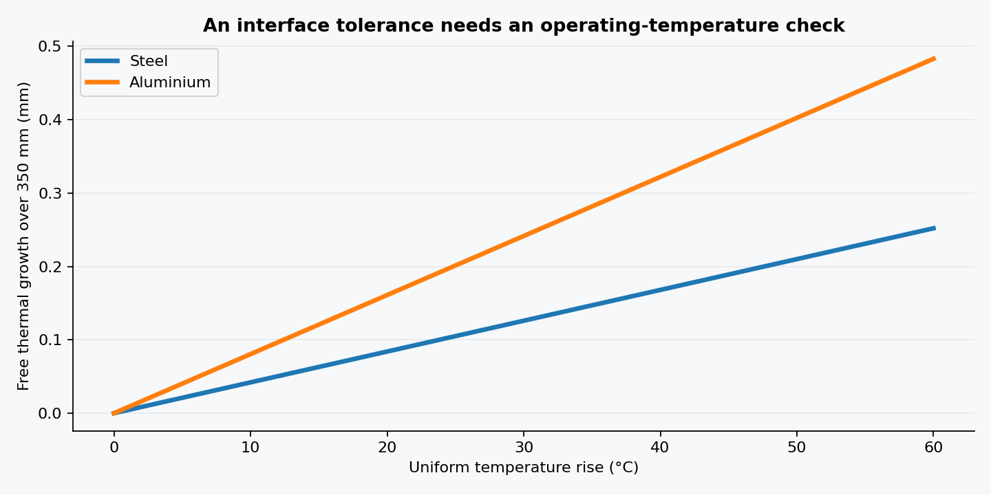
Thermal expansion follows ΔL = αLΔT for a uniform, unconstrained component with approximately constant expansion coefficient. Assume a 350 mm reference length, a 40°C temperature rise, steel α = 12 × 10⁻⁶/°C and aluminium α = 23 × 10⁻⁶/°C.
ΔLaluminium = 0.322 mm
Differential free growth = 0.154 mm
That differential is significant beside a ±0.20 mm interface tolerance. It does not automatically become a clearance loss: the direction, datum arrangement, mounting restraint and which features grow together determine its effect. If steel is fully restrained in one direction, the ideal elastic stress is EαΔT = 96 MPa for E = 200 GPa. Real restraint is usually finite, and slip, yielding or temperature gradients change the result.
Specify the dimensional reference temperature and distinguish assembly adjustment from operating movement. A clearance budget should include manufacture, thermal effects, bearing motion and elastic displacement without counting the same contribution twice.
Geometric tolerancing: control the function, not just the size
A hole can be within its diameter limits and still be in the wrong place. For a simple positional check, assume its measured centre is offset from basic location by Δx = 0.06 mm and Δy = 0.08 mm. The diametral position error is twice the radial offset.
If the specified diametral zone were 0.25 mm at regardless-of-feature-size, that centre-location result would be inside the zone. It is not a complete inspection of a long hole axis: axis orientation and the full feature extent must also satisfy the requirement in the established datum reference frame. Material-condition modifiers, datum mobility and projected zones need separate interpretation where specified.
Use flatness when the surface itself matters without a datum reference; use orientation controls when the relationship to a datum matters. Use runout controls when rotating surface behaviour matters. Choose the governing drawing standard and edition, and define a datum system that can be physically established during machining and inspection. Adding symbols indiscriminately increases cost without improving function.
Inspection uncertainty and the release decision
A measurement result includes uncertainty. Suppose independent standard uncertainties are 0.010 mm from calibration, 0.005 mm from repeatability and 0.005/√3 mm from a rectangular ±0.005 mm resolution contribution. Combine standard uncertainties in quadrature.
U ≈ 2uc = 0.02309 mm
A reported 350.190 mm result with that expanded uncertainty has an interval reaching 350.213 mm. Against a 350.200 mm upper limit, a conservative rule that requires the whole interval inside the limits cannot accept it. This does not prove the part is out of tolerance; it means conformity has not been demonstrated under that decision rule. Agree the rule, coverage and measurement method before production.
A controlled release package should connect characteristic → datum → tolerance → method → record. Prioritize critical client interfaces and rotating fits. Manage an engineering change through affected drawings, BOM entries, purchased items, work instructions and existing stock. That traceability is what turns a technically correct model into a repeatable product.
Download the worked-example calculation results (CSV) ↗
Continue exploring
General arrangement • Part drawings • Sectioned assembly • BOM • Revision notes