Impeller Design Review: Find the Risk Before Release.
An independent review of a proposed impeller revision investigated whether the change could introduce new reliability problems.
Atlas Electricals · Design experience · By Arpit Bhatt
Review the change, not just the drawing
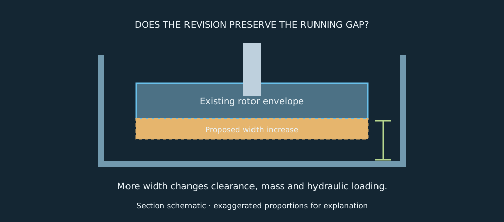
A wider impeller outlet may appear to be a direct way to influence flow. It also changes the rotating envelope, mass distribution and hydraulic loading. The independent review asked whether the proposed width increase was justified by the required duty, and whether it would reduce a critical casing clearance.
The review combined drawings, pump curves, calculations and the existing shaft, casing and motor interfaces. Its value was catching a new reliability risk before production committed to the revision.
| Basis | Value / decision |
|---|---|
| Reported concern | An outlet-width increase added rotating mass and reduced casing clearance without a demonstrated hydraulic need. |
| Reported alternative | Retain outlet width; review vane profile and trim diameter. |
| Worked-example hydraulic basis | Q = 100 m³/h, H = 30 m, η = 70%, ρ = 1,000 kg/m³. |
| Worked-example rotor basis | 5 kg rotor at 2,900 rpm; effective mass eccentricity = 0.05 mm. This is not an allowable balance limit. |
Independent hydraulic check
The starting point is conservation of energy. At the example duty, hydraulic power is ρgQH; dividing by efficiency gives shaft input.
Pshaft = 8.175/0.70 = 11.68 kW
The operating point is where the pump curve meets the system curve. A duty calculation alone does not establish that intersection, and a width increase cannot be justified by power arithmetic alone.
For a small trim screening example, reducing diameter from 200 to 194 mm gives D₂/D₁ = 0.97. Approximate trim relations give Q₂/Q₁ ≈ 0.97, H₂/H₁ ≈ 0.9409 and P₂/P₁ ≈ 0.9127: roughly 97 m³/h, 28.23 m and 10.66 kW from the example baseline.
These estimates are not a claim that the revised impeller meets the original duty. Trimming changes blade geometry and its interaction with the casing; the manufacturer’s curves and a test are needed. KSB’s impeller-trimming reference explains why the effect depends on impeller type.
Why small eccentricity matters at speed
An eccentric rotating mass needs centripetal acceleration eω². Its resulting force amplitude is F = meω². This is the physical origin of the speed-squared sensitivity of unbalance excitation.
U = me = 5 × 0.00005 = 0.00025 kg·m
F = Uω² = 23.06 N
If mass rises to 6 kg with the same effective eccentricity, force becomes 27.67 N, a 20% increase. A perfectly balanced added mass does not automatically create this force; the example deliberately holds eccentricity constant. Vibration amplitude also depends on shaft and support dynamics, damping and proximity to resonance.
Clearance deserves a separate budget. Suppose a one-sided cold gap is 1.20 mm, the geometry revision consumes 0.40 mm, dimensional variation consumes 0.20 mm and thermal/axial movement consumes another 0.25 mm. The remaining example margin is 0.35 mm. Whether that is acceptable requires the actual minimum running-clearance criterion and all movement sources. Nominal fit in CAD is insufficient.
Close the review with measurable evidence
The proposed resolution retained outlet width and adjusted vane profile and trim diameter, with review closure and inspection requirements documented. First-off checks covered bore, keyway, runout, clearance and diameter. Balance verification and performance testing completed the acceptance route.
The reported revised impeller met duty without abnormal vibration or rubbing. Its numerical balance grade, vibration limits and test curve are not supplied, so this article does not assign values to them.
- Design closure: tie each concern to a revised dimension, calculation or test requirement.
- Manufacturing closure: identify what is measured, the datum used and the acceptance limit.
- System closure: verify duty, loading and running behaviour in the assembled pump.
Core lesson: an independent review should connect geometry to function, then translate each risk into evidence that production can actually check.
Hydraulic design starts with angular momentum
The rotor changes the fluid’s angular momentum. For steady flow, torque imparted to the fluid is ρQ(r₂cᵤ₂ − r₁cᵤ₁). Multiplying by angular speed and dividing by the weight-flow rate ρgQ gives the Euler head equation: HE = (u₂cᵤ₂ − u₁cᵤ₁)/g. Here u is blade speed and cᵤ is the tangential component of absolute fluid velocity.
u₂ = πD₂n/60 = 15.18 m/s
HE = 15.18 × 12/9.81 = 18.57 m
This is an independent teaching example, not the preceding 30 m duty calculation. The assumed exit whirl cannot support a 30 m actual head at this speed and diameter even before losses. That is exactly the sort of contradiction an independent review should detect. Exit whirl must follow a physically consistent velocity triangle and blade geometry, with finite-blade slip and hydraulic losses considered.
Outlet width changes the available flow area. With blockage neglected, cₘ₂ = Q/(πD₂b₂). At Q = 100 m³/h and D₂ = 200 mm, changing width from 20 to 24 mm reduces meridional velocity from 2.21 to 1.84 m/s. It also alters the velocity triangle and clearances. Width is not an independent flow-rate dial.
Rotor dynamics: a stronger part can still vibrate
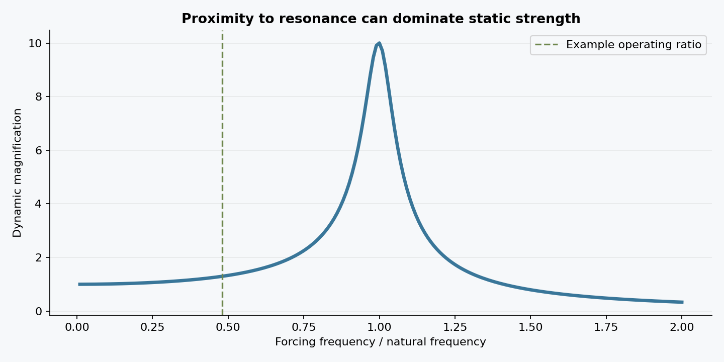
A first approximation represents the rotor as a mass on an equivalent lateral spring. From mẍ + kx = 0, the undamped natural frequency is fₙ = √(k/m)/(2π). Assume m = 5 kg and k = 2.0 MN/m; these represent a simplified mode, not a measured pump.
Operating frequency at 2,900 rpm = 48.33 Hz
r = f/fₙ = 0.480
Magnification = 1/√[(1 − r²)² + (2ζr)²] = 1.30, for ζ = 0.05
The magnification multiplies the static displacement F₀/k for a sinusoidal force of amplitude F₀. With the earlier 23.06 N unbalance-force example, the predicted displacement amplitude is approximately 15.0 μm. This simple model does not establish an acceptance limit.
Increasing mass to 6 kg at the same stiffness lowers the natural frequency to 91.89 Hz. Actual pumps have multiple bending and support modes, gyroscopic effects, bearing stiffness and operating-dependent excitation. A speed sweep, modal analysis or appropriate rotordynamic model may be needed. A favourable static stress result cannot replace a separation-margin assessment.
Make peer review a closed technical argument
For each proposed change, write the requirement, predicted effect, possible unintended consequence and closing evidence. A vane-profile revision needs a hydraulic rationale and a tested curve. A mass change needs a balance and dynamic review. A clearance change needs a dimensional and operating-motion budget. A manufacturing change needs repeatable inspection features.
Acceptance should be agreed before testing: duty tolerance, absorbed power, running clearance, allowable runout, balancing requirement and vibration measurement locations. Use the actual specification and supplier guidance for limits. Preserve the original review issue, disposition, drawing revision and first-off evidence so that a later reviewer can reconstruct why release was authorized.
Download the worked-example calculation results (CSV) ↗
Continue exploring
Review findings • Revised impeller drawing • Inspection and test requirements