Safe Changeovers: Guard the Coupling. Control the Energy.
A sewage-pump test stand had an exposed rotating coupling and no formal isolation sequence for stored pressure.
Atlas Electricals · Design experience · By Arpit Bhatt
The problem is access to energy
A coupling is a simple component with a serious interface problem: it must rotate during a test, but someone must approach it during a changeover. A removable cover addresses contact during operation. It does not prevent restart or remove pressure trapped in the pump and connected piping.
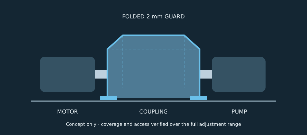
The design therefore treated the guard, its adjustment range and the isolation arrangement as one system. The objective was a changeover that remained practical while making the intended safe state visible and verifiable.
| Basis | Value / decision |
|---|---|
| Reported project inputs | 2 mm galvanized sheet; variable coupling lengths; 50 kg static-load check. |
| Mechanical approach | Slotted brackets, captive fasteners and a lockable inspection hinge. |
| Energy-control approach | Lockable motor disconnect, discharge bleed point and pressure indication. |
| Worked-example assumptions | 300 mm flat span, 300 mm effective width, steel E = 200,000 N/mm². These dimensions explain stiffness; they are not the guard’s recorded geometry. |
Why a folded guard needs more than a thickness callout
Start with the reported static mass. Weight is the force produced by gravity: F = mg. Taking g = 9.81 m/s² gives 50 × 9.81 = 490.5 N. This establishes a load case; it does not establish a certified capacity or impact rating.
To see why form matters, represent an unformed sheet as a simply supported rectangular beam strip carrying the entire force at midspan. Its second moment of area comes from integrating distance squared over the cross-section: I = ∫y² dA = bt³/12.
Mmax = FL/4 = 36,787.5 N·mm
σ = Mc/I = 183.94 MPa, with c = t/2 = 1 mm
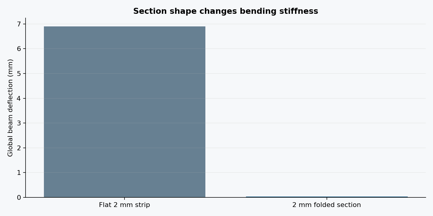
δ = FL³/(48EI) = 6.90 mm
The moment follows from support reactions F/2. The deflection follows by integrating EI y″ = M(x), with zero displacement at the supports and symmetry at the centre. The flat-strip estimate shows a sheet can be flexible even if it looks substantial.
Folds and return flanges move material away from the neutral axis, increasing I through the parallel-axis term Ad². Shorter unsupported spans help strongly because deflection scales with L³. At 6.90 mm, deflection also exceeds the sheet thickness, so the small-deflection model needs refinement; it is a screening calculation, not a final verification.
Design the interfaces around the task
Galvanized sheet suits a formed enclosure, but coating condition, cut edges, fasteners and the actual environment still need review. Slot travel must not uncover the coupling at either end of the adjustment range. Captive fasteners reduce the chance of loose hardware being lost during repetitive changes.
The model review should include the load application area, realistic bracket stiffness, fastener reactions, local sheet stress, deflection towards the rotor and mesh sensitivity. A static 490.5 N case does not assess fragment containment, entanglement reach or a person falling onto the cover.
Mechanical shielding and hazardous-energy control perform different jobs. A machine-specific procedure must identify each energy source, isolation point, stored-energy release method and verification method. A gauge reading alone cannot demonstrate that every trapped volume is depressurized. This distinction is explained in CCOHS guidance on lockout/tag out.
Verification, handover and result
The reported project used senior engineer review and observation of an actual changeover and test. The retrofit controlled routine access to the coupling and established a defined isolation sequence, adding approximately five minutes to changeovers.
- Fit: verify coverage and no rotating contact throughout adjustment.
- Structure: inspect brackets, fasteners, deflection and attachment integrity.
- Operation: confirm the approved isolation and restart procedure is usable by authorized personnel.
- Handover: issue the guard drawing, deflection check and controlled isolation procedure together.
The engineering lesson is that an easy-to-use safeguard is part of the production process. Its success depends on the hardware and the way the task is performed.
From flat plate to folded section: quantify the gain
Continue the 490.5 N example with a 300 mm-wide top plate, 2 mm thickness and two 30 mm-deep side returns beneath it. Treat the formed cover as a beam spanning 300 mm along its length. Ignore corner radii and assume the full section acts together. Coordinates are measured downward from the top surface: the top plate centroid is at 1 mm; each return centroid is at 17 mm.
ȳ = [600(1) + 120(17)]/720 = 3.667 mm
I = Σ[Icentroid + A(y − ȳ)²] = 34,800.0 mm⁴
δ = FL³/(48EI) = 0.040 mm
σmax = M(32 − ȳ)/I = 29.95 MPa
The parallel-axis theorem comes from expanding ∫(y + d)² dA about each component centroid; the cross-term vanishes. Here the returns increase section I by approximately 174 times. The result explains the advantage of forming without increasing sheet thickness. It does not include local indentation of the top panel, side-wall buckling, imperfect supports or fastener flexibility. Those can govern even when the global beam calculation is favourable.
Fasteners, slots and the real load path
The load travels from cover to brackets, from brackets to bolts and from bolts into the supporting frame. For an assumed two-bracket arrangement, each support carries 245.25 N. With two equally loaded bolts per bracket, direct shear is 122.63 N per bolt. On an assumed 6 mm unthreaded shank, average shear is F/A = 4.34 MPa. In a 2 mm sheet, nominal bearing pressure F/(td) is 10.22 MPa.
These low average values are only a first check. An eccentric bracket creates a moment: with a 40 mm offset, each bracket sees 9,810 N·mm. If a two-bolt group separated by 30 mm resists that moment as an in-plane force couple, the moment component is M/s = 327 N per bolt. Combine it vectorially with direct shear using the actual orientation. An out-of-plane moment instead introduces bolt tension and possible prying; the same shear calculation is then inappropriate.
Slots need checks for edge distance, net section, bearing and slip. If the joint relies on friction, preload and surface condition become design inputs. Do not assume a loosely tightened adjustable slot remains fixed. Define the intended retention mechanism, inspectable assembly condition and movement limit.
A verification plan that can reject the design
Use the global beam model to predict the direction and approximate size of deflection. In the detailed model, distribute the load over a realistic contact patch and represent bracket restraint honestly. Compare a shell model with the hand-check trend, then refine the mesh where load enters the sheet. Local peak stress at an ideal fixed corner may be a modelling singularity, so examine mesh convergence and the actual attachment geometry.
Acceptance requires separate criteria for deflection towards rotating parts, permanent set, retention, access prevention and the machine-specific energy-control arrangement. Review bent-edge finish and coating repair after fabrication. The 50 kg static case is one load case; it does not certify impact containment or a stepping surface. A final handover should identify the drawing revision, inspection points, approved procedure and person responsible for closing each finding.
Download the worked-example calculation results (CSV) ↗
Continue exploring
Guard drawing • Deflection check • Lockout and depressurization procedure